I had bought a SANWA CD772 Multimeter a few years ago. However, the reading is always inaccuracy.
In order to make sure everything go smooth. I sent an e-mail to Sanwa and asked for a service manual.

According to the Service manual, the calibration of the DVC required a 350mV DC input into the meter. Adjust the VR1 until it’s 350mV +- 0.2mV.
However, after I adjusted the VR1, it only improved the accuracy for the reading of 400mV DC Voltage range . For the higher DC voltage range, the reading is much lower than the reference voltage.
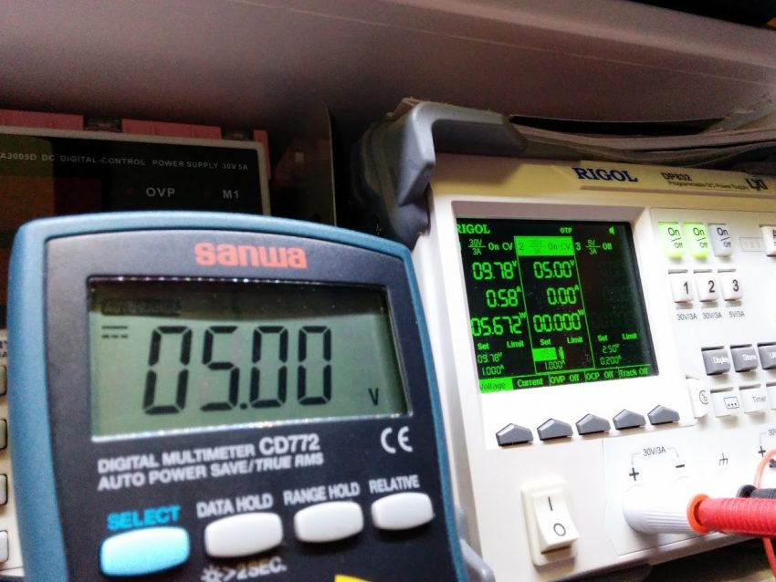
For example , When the input is a 5V DC, the meter displayed a reading of 4.96V

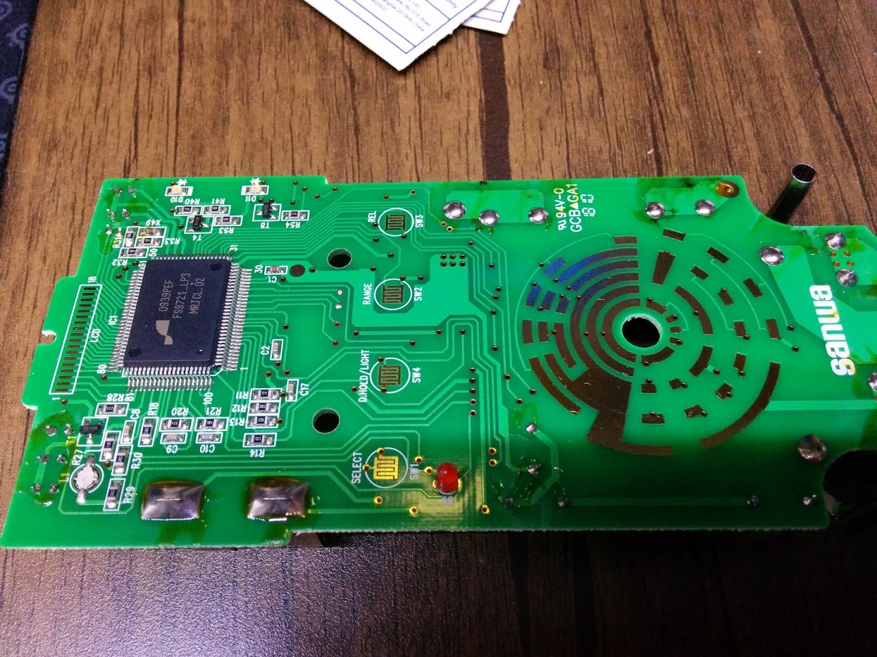
I digged into the details and found out it’s using FS9721 chipset solution

It used the same solution as FLUKE 17B . So it make no sense to having such a problem.
I took a look of the FS9721 datasheet and compare it with the sanwa PCB board and finally I found out the root of the problem.
The 10.00M ohm voltage reference divider on the Sanwa CD772 is make up by four 2.5M ohm resistance.
However, all of them are inaccuracy and having a final reading is 10.09M

let’s do some maths according to the datasheet. When we put 10.09M into the formula , we knew that the voltage go into the FS9721 = 0.49593V (match with 4.96V we got)
Voltage go into the IC [FS9721] = 5V X[1.111 / (10.09+1.111)]

I don’t have any 10.00M ohm resistance. So I use two DALE 5.00M ohm resistance to make up 10.00M ohm resistance.

Desolder those four 2.5M ohm resistance

Replaced with self-made 10.00M ohm resistance.


The sanwa multimeter is now fixed and the reading is match with the voltage reference.

Thanks for watching!
